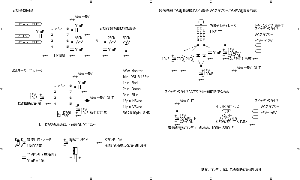

The chip legs coloured in Red are 5V in, the legs coloured in Black are GND, I get 5V and GND from the power lead that comes with the Scaler. I drew up the diagrams below (click each one to see it in full). I wanted the SLG to have all the switches, but I wasn’t worried about being able to alter the intensity of the scanlines. I actually cut it a bit larger than needed, and then shaved a slither off so that it is a very tight fit.Īlthough not necessary, I cut the excess bit of plastic away from the both openings so that the holes were square, this was so that I had flexibility when it came to squeezing the board and switches in.Ĭombing the DIY SLG and the Sync Stripper It’s not worthwhile trying to cut all the way through it, cut along it a few times and then bend it to snap it! When I’m cutting bits like this, I make sure the ruler is covering the bit I want to keep, this way, if the scalpel slips and goes off line, it doesn’t cut or mark the bit you want to keep. Yours may be different, but the measurements for my one were 43mm x 16mm. You could actually use scissors for this, but I opted for a ruler and scalpel. I cut a couple out, just in case I made any mistakes. After having a look around the house, I decided to go with a spare DVD case, sturdy enough but nice and easy to cut. I had to find something to make a back panel to slot in where the scart plug was, I planned on mounting the necessary switches and 3.5mm audio socket here. This looks perfect, I unsoldered the wires from the rear of the scart socket, and pulled the breakout cables out of the strain relief so that I could re-use it later on. Then I found this on ebay – a scart pass-thru adapter with A/V phono breakout cables.Įasy to take apart, just four clips to open, then pop it open. Ideally, I wanted it to not use a project box and instead have something which meant I wouldn’t have to cut too many holes for the scart socket, cables etc. I really wanted a box with these cables/connectors coming out of it, and to include a female scart socket, the switches to change the scanline options and the necessary Sync Separator. After a bit of hunting around, I found that they are JST PHR-12 which have a 2mm pitch. Unfortunately you do not receive the connector/cable for the VGA socket(s). Luckily the scaler is usually supplied with some cables – one for the RGB input, and another for 5V in – but if you use the normal power socket on the scaler, then the 5V in cable can be used as a 5V out cable. I really wanted to make a plug and play solution for the GBS series RGB to VGA Scaler.

This page is very out of date now, please look at GBS-Control by rama.


 0 kommentar(er)
